I made a MP3 player
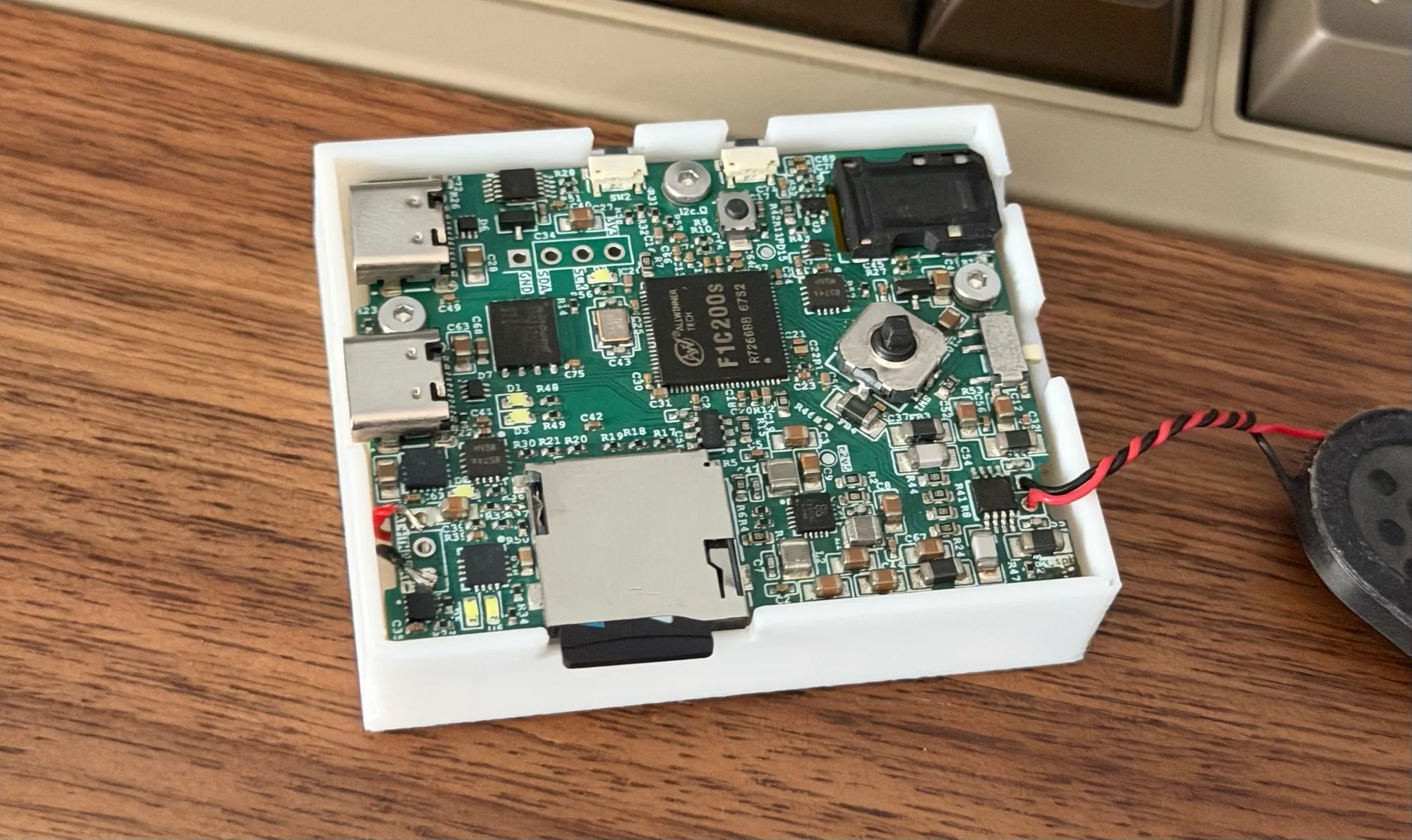
This has been cooking for a while. It started almost a decade ago,
with the first R-2R DAC I wired on a breadboard which looped 4 seconds of a 4-bit quantized 4k samples per second
“smells like teen spirit” off an AT24C16A/ATTINY13 pair.
It does not smell like teen spirit anymore,
but that idea of making my own audio player hasn’t faded.
On top of that, I have always been drawn to making portable electronics devices.
A curio. A small handmade artifact that you carry in your pocket.
So I finally made it: A MP3 player slightly larger than a matchbox. It is running a custom linux build, has a joystick for navigation, volume buttons, a SD card slot, 2 USB-C ports (one of them solely for kernel debugging), an IMU chip for shake-to-shuffle, and, most important of all, a headphone jack.
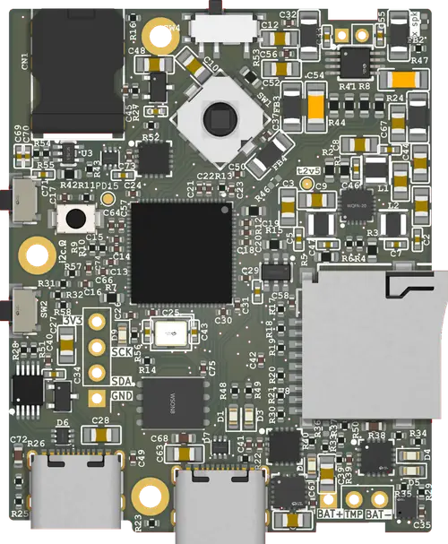
What’s also interesting is what it does not have. No display, no WiFi or bluetooth, and a simple shake-to-shuffle mechanism.
Design
I started PCB design with a rough idea of the kind of product that I wanted.
- small, with simple UX
- has a speaker: audiobook-grade is acceptable
- runs linux: can ssh into it through the USB-C port
- no bluetooth or WiFi
- no display
For a simple MP3 player, the linux requirement is probably bad design. Linux consumes much more power than purpose-written microcontroller code. A RP2040, for example, would last several times more on the same battery, while costing a lot less than a linux-capable chip.
But this is my MP3 player, and I need it to run linux. I’ve been fascinated with embedded linux for as long as I can remember, and I plan to learn a lot while putting it on my own board.
This device was shaped by a lot of competing desires. On one hand, I want a MP3 player in my pocket as soon as possible. On the other, I want to explore and learn and add as many features as possible. I want a small production-ready PCB but I want to ensure that, if parts of my schematic don’t work, the rest can still be salvaged. The defining push-pull that shaped the design was a good final product with many paths to recovery.
I also want to keep costs low. So it should be fully assembled in JLCPCB, with single side economic fabrication. I also want to use as many basic parts as possible.
PCB design and manufacturing
I didn’t expect my first shot of the PCB (fab and assembly at JLCPCB.COM) order to work so well.
It is a complex schematic, and I’d taken quite a few gambles educated guesses,
lacking the documentation or a precedent to study. Delightfully, most of them worked out in my favor.
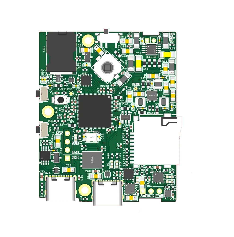
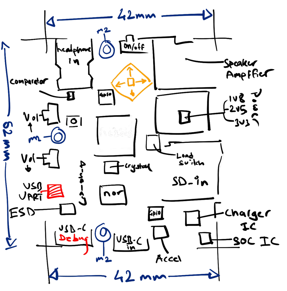
I found that the EA3036 with its 3 buck converters would be perfect to get 1v2, 2v5 and 3v3 out for the system,
based on the fact that many commercial
and hobby boards paired the two chips together.
Power Electronics News has a post with
a tried layout which I referenced heavily in my power system design.
The PAM8304 was conceptually simple to design the amplifier.
Allwinner F1C200S Chip
The F1C200S was at the exact intersection of value, ergonomics and feature-set I needed. Its built-in 64MB DDR memory and built-in cap-less1 headphone drivers, and documentation available on the internet, were enough to win me. Its boot order is also really forgiving: SD card first, NOR second. So I can easily fix “bricked ROM” without manually wiping NOR during development.
There were already schematics of linux business cards, hackaday projects, and more, using this chip.
Bugs
When I finally received the board, a lot of things just worked. I could connect the board to the PC and sunxi-fel connect to it right away.
Even toggling LEDs was a simple test through FEL.
Some bugs were bound to show up in a board of this complexity. Quickly listing:
- I wired the headphone jack as OMTP following the jack datasheet, but modern earphones are CTIA. So mic and ground were inverted. Easy fix: use a TRS jack which shorts mic and gnd anyway. I soldered the two together anyway, deciding to give up on the microphone feature
- Headphone jack_detect line was wired wrong, so the speaker only activated when headphone was connected (instead of the inverse)
- the power toggle only works on battery; when charging the system boots up anyway. I knew this going in, and took it as an okay trade off
Enclosure design

Firmware
The firmware was built using buildroot. Uboot with minor tweaks from sunxi worked well. I pulled the device tree from lichee and added my external peripherals to the mix.
static void audio_start(struct audio *a)
{
    codec_power_on(a->codec);
    codec_set_rate(a->codec, 44100);
    dma_ring_init(&a->ring, a->buf, AUDIO_BUF_LEN);
    dma_start(a->dma, &a->ring);
}&mmc0 {
broken-cd;
bus-width = <4>;
status = "okay";
};
&codec {
allwinner,pa-gpios = <&pio 4 12 GPIO_ACTIVE_HIGH>;
status = "okay";
};make f1c200s_mp3_defconfig
make -j"$(nproc)"
sunxi-fel -p spiflash-write 0 output/images/flash.binFootnotes
-
Since audio swings both positive and negative, most headphone drivers require capacitors to pump headphone ground to 1/2VPP, but F1C200S does not ↑